


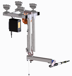
Hubachse ZH90 bodenverfahrbar mit Schraubtechnik
Hubachse ZH90 bodenverfahrbar mit Schraubtechnik
Guide · Handling techniques
THE REACTION MOMENT WHEN SCREWING ON THE LIFT AXLE
A torque value in the datasheet says little about the actual bolting application. What matters is how torque, load, and stroke interact, and how the lifting axis reliably dissipates the counter-torque. For cases where a standard system can no longer handle the required torque, we design custom solutions.
CHAPTER 1
What really happens when you're screwing something
When tightening a screw, the tightening torque acts on the connection. According to the principle of action equals reaction, an equal and opposite counter-torque acts back on the screw tool. This reaction torque must be absorbed somewhere. With handheld screwdrivers, this is done by the operator's arm, which becomes ergonomically problematic at a few Newton meters and unacceptable at higher torques.
On a lifting axis, the reaction torque is not transferred to the person, but rather via the rigid linear guide into the structure and the rail. This is precisely what makes the lifting axis the load-bearing basis for screw applications. The question is not whether, but how much torque, in which direction, and at which stroke it absorbs.


CHAPTER 2
How the reaction moment is calculated
The reaction torque corresponds to the tightening torque and follows the basic formula of mechanics. The torque is the product of force and vertical lever arm.
M = F xr
(M moment in Nm / F force in N / r vertical lever arm in m)
If the force does not act perpendicularly, only its perpendicular component matters. Then the general formula M = F × r × sin α applies. The moment is at its maximum at 90 degrees and vanishes at 0 degrees. In practice, this means two things. First, lengthening the lever arm increases the moment for the same force. Second, and this is the crucial point for the lifting axis: the distance from the screw point to the guide is itself a lever arm. It increases with the stroke and thus amplifies the forces introduced into the guide and structure.
A numerical example makes this tangible. A reaction torque of 1,300 Nm, supported over a guide distance of 0.3 m, generates a lateral force of approximately 4,300 N at the guide. If this distance doubles due to a larger stroke, the force doubles. This is precisely why the direction of the torque and the most unfavorable stroke point are part of every sound design.


CHAPTER 3
Three sizes, one load case
A single Nm value in the datasheet almost never describes the actual tightening condition. Three quantities are interdependent and must be considered together.
Size 1
TORQUE
Height and direction of the reaction moment. When screwed horizontally, the guide is subjected to bending; when screwed vertically, torsion – two different load cases.
Size 2
LAST
The weight simultaneously supported by the tool, holder, and component. This adds to the forces resulting from the reaction torque.
Size 3
HUB
The further extended, the longer the lever arm. With a large stroke, the permissible load and transmissible torque decrease noticeably.
A catalog value of approximately 2,500 Nm may apply to a short stroke and a central load, but in real-world applications with a stroke of over one meter and a horizontal moment direction, this value will be significantly lower. Therefore, the crucial factor in a screw application is not the maximum load capacity, but rather the moment at the most unfavorable point of the stroke.
CHAPTER 4
Screwed horizontally or vertically
Screw vertically
Direction of moment: about the vertical axis
Guide stress: Twisting
Recording via: anti-rotation device, chassis
Constructive effort: moderate
Horizontal screws
Direction of moment: about the horizontal axis
Stress on the guide: Bending
Admission via: Leadership, structure, connection
Constructive effort: higher
Reputable data sheets provide separate values for horizontal and vertical moments. Anyone who only gives one value omits the more critical direction. The direction of the moment during the process must be determined before any design work begins.
CHAPTER 5
When manual methods are no longer possible
There is no fixed Nm limit for the obligation to use a support. The decisive factors are the type of screwdriver, the frequency of use, and the working posture. The type of screwdriver determines how strongly the reaction torque is transmitted to the worker.
Stick screwdriver
Reaction moment at the worker: high, rotates in the hand
Support is useful from the low single-digit Nm range.
Pistol screwdriver
Reaction time at the worker: medium, more easily grasped
Support is advisable from the mid-single-digit Nm range.
Angle screwdriver
Reaction moment at the worker: easily absorbable via the lever
Support is advisable from the higher double-digit Nm range.
Impulse screwdriver
Reaction time at the worker: very low due to short impulses
Usually usable without support
At high torques or with frequent repetition, having the operator absorb the reaction torque is neither ergonomically acceptable nor process-reliable. In such cases, a support takes over. A distinction must be made between a simple torque support, which only absorbs the torque, and a load-bearing lifting axis, which additionally guides the load without pendulum motion over a long stroke. For the combination of high torque, medium load, and long stroke, the lifting axis is the appropriate solution.
CHAPTER 6
When the modular system reaches its limits: That's exactly where we begin.
Modular standard systems specify their Nm values for an ideal case. If a real-world bolting application encounters the critical combination of high reaction torque, medium to heavy load, and large stroke, they reach their limit, and the inquiry remains unanswered.
Zeilhofer designs precisely these cases, individually rather than using off-the-shelf solutions. We integrate the lifting axis into an existing rail system, even with third-party products and their chassis, and adjust it to the required moment in its direction. This way, your installed infrastructure remains usable while the momentary load is reliably handled.
CHAPTER 7
Further bases for screwing processes
The lifting axis is the right base when the component is suspended from a rail and bolted to it. Depending on the installation situation, however, other systems can also absorb the reaction torque. Which base is suitable for your process depends on the installation situation, movement requirements, and available installation space.
Suspended from rail: lifting axle
-
Swing-free lifting on the Z-axis and momentary recording via the rigid guide. Ideal for existing rail systems and large strokes.
Free in space: Joint manipulator
-
It absorbs off-center loads and torques up to 800 kg and positions the component in multiple axes when working in a manner other than vertical.
Freestanding on the ground: Mobile floor trolley
-
It transfers the reaction torque into the ground via the structure and base. Suitable for locations where no rail is present or load-bearing.
Specific applications are shown in the articles "ZH90 lifting axis in screw assembly" and "movable floor trolley for bolting ." The fundamental distinction between the systems is discussed in the guide "Manipulator, crane or chain hoist ."
CHAPTER 8
What is needed for a reliable interpretation
To ensure that a lifting axis can reliably handle a screw application, instead of being measured against a catalog number, we clarify these points in advance:
-
Maximum reaction moment and its direction, horizontal or vertical
-
Required stroke and the most unfavorable point in the stroke range
-
Simultaneously carried load from tool, fixture and component
-
Mounting flange and carriage for holding the screwdriver
-
Connection to existing rail systems, trolley frames and chassis, including those of other manufacturers
-
Swivel joint around the Z-axis, lockable to fixed angles if required.
-
Interaction with existing drive systems, such as a customer-supplied rope balancer
-
Control, position monitoring and marking of the screw position
Zeilhofer Handling Technology designs each screw application specifically for these dimensions, rather than relying on a fixed modular system. The ZH90 lifting axis supports loads up to 1,200 kg without oscillation on the linear Z-axis and is specifically designed for the required reaction torque in screw applications, including the connecting flange and carriage. All this is manufactured in-house, ISO 9001 certified, and TISAX Level 2 compliant with prototype protection.
CHAPTER 9
A snapshot is only half the battle.
A system that only absorbs the reaction torque does not automatically make the screwing process safe. Upon request, Zeilhofer combines the lifting axis with an integrated control system that safeguards the entire process. This distinguishes a properly designed screwing solution from a simple support.
Screw connection verified
-
The control system checks whether each screw has been tightened correctly and with the correct torque. Only after successful tightening does it allow the next step.
Tool monitored
-
Monitored storage positions and a holder indicate the correct tool to the operator. The movement can only be released with the correct bit or socket wrench.
Release logic in sync
-
The position and sequence of the screw points are stored in the control system. This ensures the correct sequence and increases cycle time and process reliability.
From a single source
-
Structure, guidance, connection, fixture and control system all come from a single manufacturer. ISO 9001 certified, TISAX Level 2 compliant with prototype protection, Made in Germany.
FAQ / Q&A
FREQUENTLY ASKED QUESTIONS
01 What is the reaction torque when screwing?
When tightening a screw, the tightening torque acts on the screw, and an equal counter-torque acts on the tool. This counter-torque is the reaction torque. It must be supported; otherwise, the tool, along with the operator or support device, will rotate. At the lifting axis, it is transferred to the structure via the rigid guide.
02 Which lifting axis can handle 1,300 Nm?
This doesn't depend on a single catalog value, but rather on the combination of torque, load, stroke, and torque direction in the specific application. A high Nm value often only applies to short strokes and light loads. Zeilhofer designs the lifting axis for the actual bolting application, including the connecting flange and carriage.
03 How do you calculate the reaction moment?
The reaction torque corresponds to the tightening torque and follows the formula M = F × r, force times vertical lever arm. If the force acts at an angle, M = F × r × sin α applies. For the lifting axis, the distance from the screw point to the guide is also crucial, as this lever arm increases with the stroke.
04 Why does the torque decrease with increasing stroke?
The further extended, the longer the lever arm between the screw point and the guide. The reaction torque generates greater forces and deformations. Therefore, with a large stroke, both the permissible payload and the transmissible torque decrease. A robust design considers the most unfavorable point in the stroke range.
05 What is the difference between tightening torque and maximum tool torque?
The tightening torque is the target value with which a screw is tightened. The maximum tool torque is the highest value the screwdriver can deliver. For support purposes, the actual effective reaction torque during the process is what matters, and this may be lower. These two values should not be considered equivalent.
06 At what torque level must a screwdriver be supported?
There is no fixed limit; the type of screwdriver, frequency of use, and working posture are the determining factors. With straight screwdrivers, support is advisable even at low torque values (Nm), while with angle screwdrivers, it's only necessary at significantly higher torque values. At high torques or with frequent use, a support or lifting axis takes over.
07 What distinguishes a torque support from a lifting axis for screw applications?
A torque support only absorbs the reaction torque and cannot bear a heavy load over a long stroke. A lifting axis combines both: pendulum-free lifting on the Z-axis and absorption of the reaction torque. For high torque, medium load, and long stroke, the load-bearing lifting axis is the appropriate base.
08 Can a lifting axis be connected to an existing third-party rail system?
Yes. Using a suitable trolley frame and carriage, the lifting axis can be connected to existing rail systems, even those from other manufacturers. This allows the installed rail system to remain usable while the lifting axis is specifically designed for the required reaction torque.
READ MORE
FURTHER GUIDES ON THIS TOPIC
In-depth guides and applications on related topics in handling technology.
APPLICATION
ZH90 in screw mounting
Non-oscillating screw fastening in automotive manufacturing, with mounting for pneumatic screwdrivers, electric screwdrivers and spindles.
APPLICATION
Mobile floor trolley
Screw mounting freestanding on the ground, without a rail, with reaction torque absorption via its own base.
BASICS
manipulator, crane or chain hoist
Which lifting system is worthwhile for which task, in an objective comparison according to load capacity, drive and degree of automation.
COMPONENTS
Screwdriver & Screw Spindle
Integration of screwdrivers and screw spindles into the lifting aid, with IO-Link and fieldbus connection.